Defining AC and DC Charging Technologies
AC and DC chargers differ less by the plug the driver sees and more by where the power conversion happens.
How AC Charging Works
Alternating Current charging sends AC power from the building supply to the vehicle. The vehicle then uses its onboard converter to change that power into DC before it reaches the battery. In commercial installations, AC units commonly sit in the 7-22 kW range, which makes them practical for workplaces, managed car parks, and long-stay tenant bays.
The charger itself is comparatively simple. It provides controlled power delivery, safety monitoring, communications, metering, and access control, but the heavy conversion stage remains inside the vehicle.
How DC Charging Works
Direct Current charging moves the conversion stage out of the vehicle and into the charging station. The station rectifies the incoming AC supply and delivers DC power directly to the battery terminals through the vehicle’s charge control system.
That is why a DC unit has a larger enclosure, heavier internal components, stronger cooling requirements, and more demanding electrical protection. A 50 kW DC rapid charger is not just a faster pedestal. It is a power conversion cabinet, cable management system, communications device, and safety-controlled electrical asset in one package.
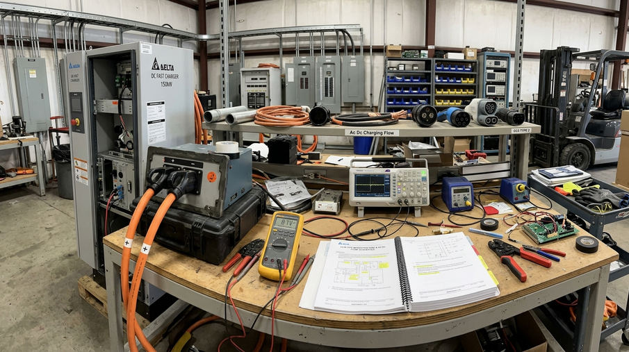
Main point: AC charging depends on the vehicle’s onboard converter; DC charging brings the converter into the station and pushes power directly toward the battery.
The Commercial Infrastructure Challenge
For facility managers, the hard question is not usually “AC or DC?” It is “how much charging can this site support without turning a tidy car park project into a major electrical upgrade?”
Capital Cost Meets User Demand
Tenants and staff tend to ask for visible charging capacity. Finance teams ask for controlled capital expenditure. The electrical system sits between both demands and sets the real boundary.
AC pedestals suit staged deployment because the loads are smaller and easier to distribute. DC rapid chargers answer a different requirement: fast turnover, fleet readiness, or public charging income. The mistake is to treat both as interchangeable line items on a procurement schedule.
Existing Boards, Protection, and Compliance
High-capacity chargers place new stress on existing commercial infrastructure. Distribution boards, spare ways, earthing arrangements, cable routes, containment, discrimination, and metering all need checking before a charger model is selected.
BS 7671 18th Edition Amendment 2 requires RCD protection on EV circuits, and DNO notification is required for any installation exceeding 3.68 kW per phase. That threshold is quickly crossed in commercial work, so DNO engagement should not be left until the contractor is ready to excavate.
For sites considering funding support, the official Workplace Charging Scheme guidelines should be checked against the intended use, ownership model, and installation timing.
Warning: Overloaded single-phase supplies in older buildings trip breakers within minutes of simultaneous DC sessions. If a building still carries legacy distribution, confirm the supply arrangement before promising rapid charging to tenants.
Analyzing Power Requirements and Grid Constraints

The load assessment should start at the main incomer, not at the parking bay.
Three-Phase Requirements
Commercial DC rapid chargers require a much stronger supply profile than standard AC units. A 50 kW DC unit needs a 400 V three-phase supply, and the upstream equipment must be able to carry that demand alongside the building’s normal load.
AC units can often be spread across phases and managed through load balancing. That does not remove the need for design work, but it gives the installer more options. DC charging concentrates demand more aggressively, which is why cable sizing, protective devices, and available capacity need to be checked as a system.
Site Capacity Assessment
A practical survey follows a fixed sequence:
- Record the existing supply type and main protective device.
- Review current maximum demand from available metering and building usage patterns.
- Inspect the main distribution board for spare ways and thermal headroom.
- Map the cable route from the intake position to the proposed charger bays.
- Model charger demand with load management applied.
- Submit the DNO application or notification before procurement is locked.
For sites under 100 kVA, a DNO application review window on the order of 4-8 weeks is a sensible programme allowance. That period can determine whether chargers arrive on time or sit in storage while the project waits for permission to connect.
While standard load assessments cover typical commercial setups, sites with heavy industrial machinery require specialized harmonic analysis before adding DC chargers.
Design note: Rural sites with overhead lines can experience voltage drop exceeding 5% at 50 kW draw. Treat distance from the supply point as a design variable, not a routing detail.
Cost Analysis: Installation vs. Long-Term ROI
AC is normally cheaper to install; DC can be easier to monetise where drivers need a fast stop. The right answer depends on who is charging, how long they stay, and whether the site can support the load without major reinforcement.
Upfront Costs
AC pedestal hardware and groundworks typically complete in the ballpark of 2-3 days per unit where routes are straightforward and the board has capacity. The civil work is usually modest: bases, ducting, feeder cables, protection, commissioning, signage, and bay marking.
DC rapid charging changes the scope. The charger body is more expensive, the cable route is heavier, and the electrical design carries less tolerance for shortcuts. DC rapid units require a 35 mm² minimum cable cross-section, and that affects trench sizing, bending radius, containment, and termination space.
Hidden DC Costs
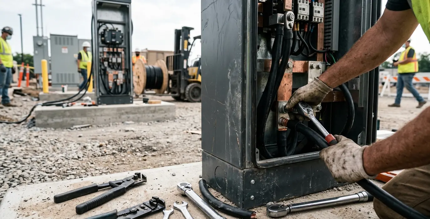
The charger price is rarely the full DC budget. The site may need larger switchgear, upgraded protection, revised metering, new feeder pillars, or a substation upgrade. Groundworks can also expand when the most convenient bays are not the best electrical location.
One useful comparison is to price two layouts before committing: the driver-friendly layout and the cable-efficient layout. If they differ heavily, the design team can then decide whether the improved user experience justifies the extra trenching and reinstatement.
ROI Models
Paid public charging relies on utilisation. A retail park or mixed-use commercial site may recover investment through charging revenue when drivers regularly need short, high-power sessions.
Workplace and tenant charging often earns its keep differently. It supports staff convenience, fleet electrification, tenant retention, and building marketability. Those benefits are real, but they should be costed honestly: connection charges, maintenance, back-office software, payment processing, inspection, and electricity tariff exposure all belong in the model.
Matching Charger Types to User Dwell Times
Dwell time is the period a vehicle naturally remains parked. It is the most useful early filter for charger selection.
Long-Stay Commercial Parking
Workplaces with 8-hour parking periods are usually best served by multiple 7-22 kW AC chargers. The vehicle is parked long enough for slower charging to be useful, and the site benefits from spreading electrical demand across more bays.
This approach also avoids the common complaint that one rapid charger becomes a queue point. Ten AC bays can serve a wider group of staff over the day, especially when access rules and load management are configured properly.
Short-Stay and High-Turnover Sites
Retail parks, logistics hubs, and short-stay commercial sites operate differently. A driver parked for a 30-45 minute turnover window will not get the same practical value from a low-power AC socket. In those settings, 50 kW+ DC rapid chargers align better with the visit pattern.
Fleet depots sit between the two categories. Pool vehicles may need a rapid top-up during the day, while staff cars can charge slowly in the background. A hybrid design often works better than a single charger type forced across every bay.
Main point: Match charger power to parking behaviour first, then refine the electrical design. Starting with hardware brochures usually leads to over-specified DC or under-served AC bays.
Step-by-Step Implementation Strategy
A commercial landlord should treat EV charging as a small infrastructure project, not an accessory purchase.
Procurement and Installation Sequence
- Initial site survey: Confirm supply capacity, distribution board condition, cable routes, parking layout, earthing, lighting, drainage, and user access requirements.
- Concept design: Select AC, DC, or hybrid charging based on dwell time, electrical capacity, and commercial use.
- DNO approval: Submit the planned connected load, charger ratings, site drawings, and load management strategy.
- Groundworks: Excavate trenches, install ducts, prepare bases, and reinstate surfaces before chargers arrive.
- Electrical installation: Fit switchgear, protective devices, cabling, chargers, signage, and metering.
- Software commissioning: Configure tariffs, RFID access, payment settings, reporting, load balancing, and remote monitoring.
- Handover and testing: Complete compliance & testing records, user instructions, asset registers, and maintenance schedules.
What to Do Early
Future-proof the underground works. Installing 110 mm draw pits at 15 m intervals during the first trenching phase keeps later expansion practical. Retrofitting ducts through a finished car park is almost always more disruptive than installing spare capacity when the ground is already open.
In one regional project, the initial load survey showed spare capacity on the main distribution board, so the team retained the existing 400 A incomer rather than pursuing a substation upgrade. The useful lesson is procedural: verify measured capacity before assuming reinforcement is unavoidable.
What to Avoid
- Ordering chargers before the DNO position is known.
- Placing rapid chargers where cable routes are longest unless the commercial case justifies it.
- Ignoring back-office software until the electrical work is complete.
- Leaving bay marking, signage, and user access rules until handover week.
- Installing ducts that only suit the first phase of chargers.
Software commissioning can be completed within a window hovering around 5 working days after DNO sign-off when payment accounts, network connectivity, charger serial numbers, and access policies are prepared in advance.
A Fully Worked Commercial Installation Case
Use this as a practical blueprint for a 50-space office park that needs staff charging and fleet vehicle turnaround.
System Design
The office park installs ten 7 kW AC chargers for staff and two 50 kW DC rapid chargers for fleet vehicles. The hybrid array connects through a 200 A three-phase feeder with dynamic load management, so the system can reduce charger output when the building load rises.
The AC chargers are placed in staff bays closest to the office entrance but still within an efficient cable route. The two DC units are positioned near the fleet parking area, where vehicles can enter, charge, and leave without blocking long-stay bays.
Replicable Delivery Sequence
- Mark ten staff bays and two fleet bays on the proposed layout drawing.
- Survey the intake position, main distribution board, and route from the switchroom to the car park.
- Submit one DNO application covering the full hybrid array rather than splitting AC and DC requests.
- After DNO approval, install the 200 A three-phase feeder, duct routes, draw pits, charger bases, and feeder protection.
- Mount the ten 7 kW AC units first, then install the two 50 kW DC units once the heavier cabling route is complete.
- Configure dynamic load management so staff charging yields capacity when fleet rapid charging is active.
- Commission the software with two user groups: staff RFID access for AC charging and fleet-authorised access for DC charging.
- Test RCD protection, charger communication, payment or access records, emergency isolation, and load response under simultaneous charging.
The final handover pack records the DNO approval, circuit schedules, test certificates, charger serial numbers, software settings, and bay allocation plan: ten staff AC bays on managed access, two fleet DC bays on priority load, all controlled through the same back-office platform.