Table of Contents
- The Shift Toward Commercial Solar PV
- Domestic vs. Commercial Solar Infrastructure
- Assessing Your Existing Electrical Infrastructure
- Grid Connection Constraints and Compliance
- Step-by-Step Integration Process
- Off-Grid Capabilities and Energy Storage
The Shift Toward Commercial Solar PV
Why commercial sites are moving beyond grid-only supply
Commercial solar PV is no longer a bolt-on sustainability gesture. For many sites, it has become part of the core electrical infrastructure conversation, sitting beside incoming supply capacity, load growth, resilience planning, and future plant upgrades.
Rising energy costs usually start the discussion. Sustainability targets keep it moving. The practical driver, though, is control. A commercial building that can generate part of its own power has more options than one fully exposed to grid tariffs and local network constraints.
The shift is not always toward full off-grid operation from day one. Most projects sit somewhere between traditional grid reliance and partial energy independence. A warehouse may use solar PV to cover daytime base load. A small manufacturing site may pair PV with storage to protect selected circuits. A larger facility may design for eventual islanding of critical operations.
What changes technically
Commercial PV starts to look different as soon as the numbers rise. Three-phase arrays commonly use inverters sized from 30 kW upward, and panel strings are often configured in the 600-1000 V DC operating range. That voltage band affects cable selection, isolation, labelling, containment, and the working method used during commissioning.
Photovoltaic panels are the visible part. The real integration work happens behind the scenes: inverter placement, AC protection, DC isolation, export control, switchgear capacity, metering, and distribution board coordination.
Key Takeaway: Treat commercial solar PV as an infrastructure project first and a panel installation second. The roof matters, but the plant room usually decides whether the system can be connected cleanly.
Domestic vs. Commercial Solar Infrastructure
Scale changes the rules
A domestic solar installation may involve a single-phase consumer unit, shorter cable runs, and a smaller inverter. Commercial infrastructure brings a different set of tolerances. Three-phase distribution boards rated 400 A or higher are common territory, and cable runs through plant rooms may need planning around 25-50 mm² cross-section conductors.
That does not just mean heavier cable. It means more space, larger bend radii, more careful segregation, stronger containment, and better coordination with existing services. A route that looks tidy on a domestic job can become unworkable once it passes through a plant room with HVAC pipework, fire stopping, data cabinets, and restricted maintenance access.
Where domestic precision still matters
The best commercial solar work often borrows habits from meticulous domestic electrical work. Garden office power, AV cable routing, external lighting, and data cable installation all teach the same lesson: the finish is decided before the first hole is drilled.
SDM Electrical’s recognized domestic work, featured in Ashlyn Gibson’s book within a domestic design and workmanship context, is a useful benchmark here. Not because a commercial PV array is the same as a garden office supply. It is not. The point is discipline: clean routing, documented decisions, careful containment, and respect for how a finished space will be used after the installer leaves.
Community observation suggests that clients notice neatness first, but engineers value traceability later. On commercial solar PV, both matter. A beautifully installed inverter bank is still a maintenance problem if nobody can identify the isolator path, access the terminals, or understand the export control arrangement.
Common mistake: scaling domestic thinking without changing the design
- Using domestic-style cable routes where mechanical protection and future access are inadequate.
- Underestimating containment size once AC, DC, data, metering, and control cabling share the same plant room area.
- Leaving insufficient space around distribution boards that may later need export limitation, metering, or storage integration.
- Assuming a neat consumer-unit method translates directly to a three-phase commercial board.
Pro Tip: Before pricing containment, walk the full route with someone who understands both electrical loading and building fabric. The awkward section is rarely shown properly on the first plan.
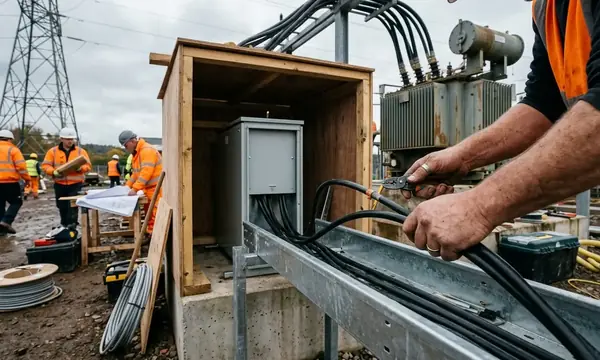
Assessing Your Existing Electrical Infrastructure
Start with supply capacity, not inverter location
The first serious assessment should focus on the main incoming supply capacity before anyone gets attached to inverter placement options. I compare regional standards often, and this is where the same pattern appears: the design that looks elegant on paper can stall if the supply head, switchgear, or distribution arrangement cannot support reverse power flow.
A practical survey starts in the intake room. Check the main supply, metering arrangement, main switchgear, distribution boards, spare ways, earthing, bonding, protection settings, and existing load profile. Only then does inverter placement become a useful discussion.
Switchgear inspection for a commercial solar PV integration is often completed in 3-5 working days, depending on access and the state of existing records. That time is not padding. It is where hidden constraints turn up: undocumented submains, crowded trunking, tired breakers, missing labels, and distribution boards that have been altered too many times without a clean update to the schematic.
Reverse power flow needs deliberate protection
Traditional commercial distribution assumes energy flows from the grid into the building. Solar PV changes that. When generation exceeds local demand, power can flow back toward the network unless export is limited or controlled.
Reverse power flow relays are commonly set to trip at 105% of rated export. The exact arrangement depends on the approved export capacity, inverter settings, protection coordination, and DNO requirements. Do not treat it as a checkbox buried in commissioning. It affects the whole integration method.
Warning: Overlooking cable derating in high ambient temperatures leads to overheating. Plant rooms, roof voids, and sun-exposed containment can all push cable temperatures beyond the neat assumptions made at desk stage.
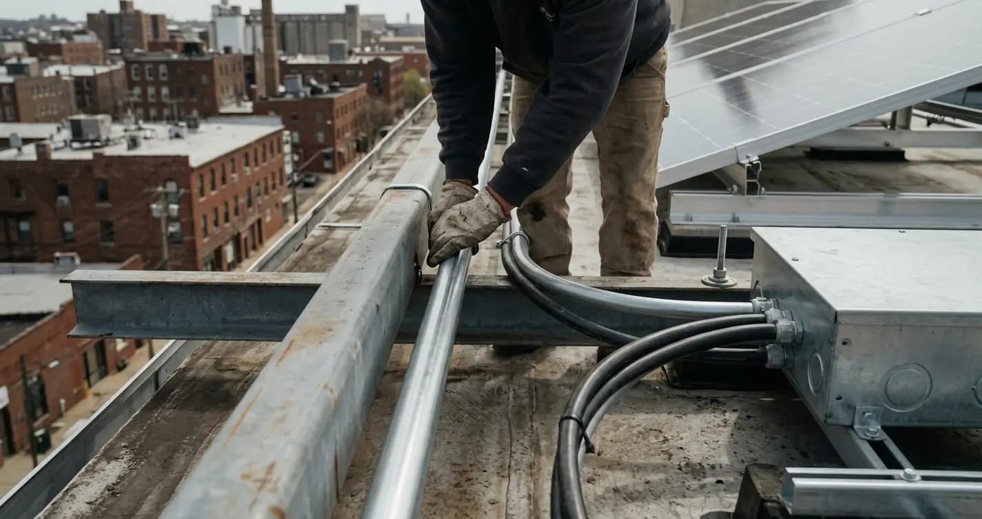
Route planning from rewires and data networks
Good cable routing has more in common with accessibility rewiring and commercial data networks than many PV drawings admit. You need a route that can be installed safely, inspected, maintained, and expanded without dismantling half the building.
For commercial PV, I would normally mark routes in layers:
- Primary DC routes from array zones to junction points or inverter positions.
- AC routes from inverters to the main commercial distribution board.
- Control, metering, and communications cabling for monitoring and export control.
- Future pathways for battery storage, additional inverters, or backup circuits.
The drawing is not only for the installer. It becomes the first maintenance map for the facilities team.
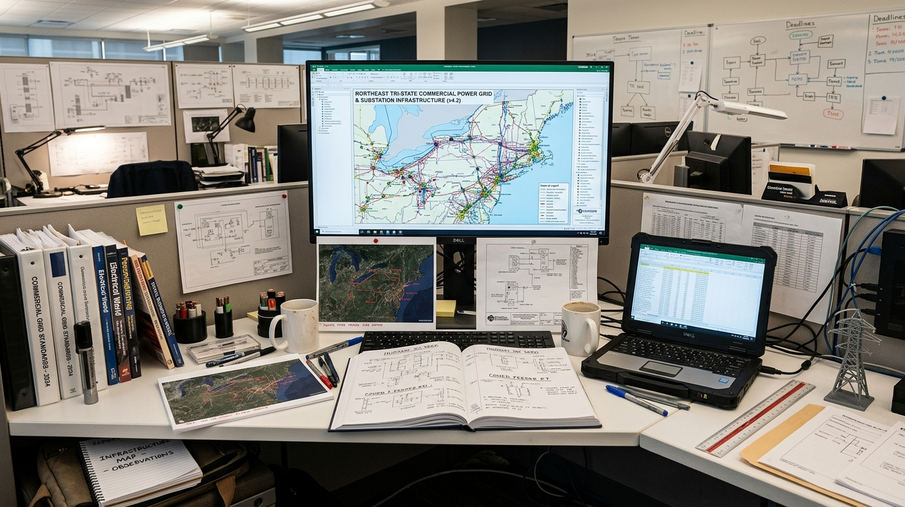
Grid Connection Constraints and Compliance
The grid may be the limiting factor
A commercial roof may have space. The electrical network may not. That is the part clients sometimes find frustrating, especially when the building load appears large enough to absorb much of the PV generation.
One catch: export is limited to 3.68 kW per phase without prior DNO agreement. For commercial systems, that limit is usually reached quickly, so the DNO conversation should happen early, not after the equipment has been selected.
DNO application processing commonly takes 8-10 weeks. That timeframe affects procurement, scaffold planning, shutdown windows, and commissioning dates. It also means the design team should avoid promising a connection date before the network operator has responded.
G99 is not paperwork at the end
Commercial generation generally falls under G99 requirements. The Energy Networks Association (ENA) G99 guidelines set the framework used by network operators for distributed generation connections.
G99 compliance requires witness testing at commissioning. That has practical consequences. Protection settings must be ready. Documentation must match the installed system. The right people need to be present. If the commissioning file is assembled the night before, the test becomes harder than it needs to be.
What to avoid during approval
- Submitting an application before confirming the proposed export strategy.
- Changing inverter models after approval without checking whether the DNO needs updated information.
- Assuming one regional network operator will apply the same interpretation as another.
- Leaving witness testing arrangements until the final commissioning week.
Variations in regional grid codes require site-specific DNO consultation. The local network often has the last word, particularly where older infrastructure or constrained export capacity is involved.
Step-by-Step Integration Process
A practical sequence that keeps the job controlled
The cleanest commercial solar PV integrations follow a deliberate order. Not a rigid script, but a sequence that stops roof work, plant room work, compliance, and shutdown planning from pulling against each other.
- Confirm the electrical survey. Validate main incoming supply capacity, switchgear condition, distribution board suitability, and spare capacity for PV connection.
- Lock the DNO position. Confirm export limits, protection requirements, witness testing expectations, and any site-specific conditions.
- Plan inverter locations. Select positions with safe access, short practical cable routes, and enough ventilation.
- Coordinate DC routes. Keep cable runs protected, labelled, and accessible, especially where they pass through roof penetrations or shared service zones.
- Install isolation and protection. Fit DC and AC isolators in positions that make sense during both normal operation and emergency work.
- Integrate into the main distribution board. Connect through the approved protection arrangement, meter correctly, and document every change.
- Commission with records open. Test, label, verify settings, and leave the site with drawings that match the installation.
Inverter placement is a maintenance decision
Inverters need airflow and access. Mounting commercial inverters with clearance in the ballpark of 600 mm for airflow is a simple requirement that prevents avoidable overheating and service frustration. The temptation is to use any spare wall. Resist it.
Think like the engineer who will attend during a fault. Can they open covers safely? Can they isolate without reaching behind live plant? Can they read labels under normal lighting? Can heat escape when the room is already warm from other equipment?
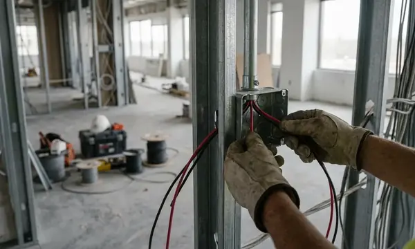
Isolation and distribution board integration
DC isolators rated IP65 should usually sit on the order of 2 m from array junction boxes. That placement makes isolation clear at the array side and reduces confusion during maintenance or emergency attendance.
On the AC side, heavy-duty isolation and suitable protection must align with the distribution board arrangement. The physical connection into the main commercial distribution board is where design discipline becomes visible. Poor labelling, cramped glanding, or unclear protection settings make the whole installation harder to trust.
Key Takeaway: The commissioning engineer should not have to interpret your intentions. The installation should show them.
Off-Grid Capabilities and Energy Storage
Storage changes the aim of the system
Solar PV reduces imported energy. Battery storage can change when and how that energy is used. For commercial facilities, that distinction matters.
Commercial battery banks are often configured around 48 V nominal modules, with modules hovering around 100-200 Ah used as building blocks. The design question is not simply how much storage can be fitted. It is which loads deserve support, for how long, and under what operating conditions.

Critical operations first
True off-grid energy independence is rarely an all-or-nothing target on the first phase. A more grounded approach is to identify critical facility operations: security systems, network cabinets, access control, essential lighting, refrigeration controls, or process equipment that cannot tolerate abrupt loss of supply.
When storage and transfer equipment are designed correctly, a transfer switch can operate on the order of 20 ms during grid loss. That is fast enough for many continuity strategies, but the protected circuits still need careful selection. Some loads behave badly during transfer. Motors, inrush-heavy plant, and mixed legacy equipment need closer review.
Future-proofing against outages
The best time to plan storage pathways is during the PV integration, even if batteries come later. Leave space in the plant room. Reserve containment routes. Think about ventilation, fire strategy, metering, control cabling, and how the system will be isolated during maintenance.
What to do now:
- Mark future battery locations on the electrical layout.
- Allow for additional control and monitoring cabling.
- Separate essential and non-essential loads where practical.
- Document how the site should behave during grid loss.
What to avoid:
- Promising full off-grid operation before load priorities are agreed.
- Installing PV with no spare pathway for storage cabling.
- Assuming all commercial loads can transfer cleanly without review.
- Leaving facilities staff without a plain-English operating sequence.
Commercial solar PV works best when it is designed as part of the building’s electrical future, not as a standalone generation asset. Get the infrastructure assessment right, respect the DNO process, leave room for storage, and the system becomes easier to maintain as the site grows.