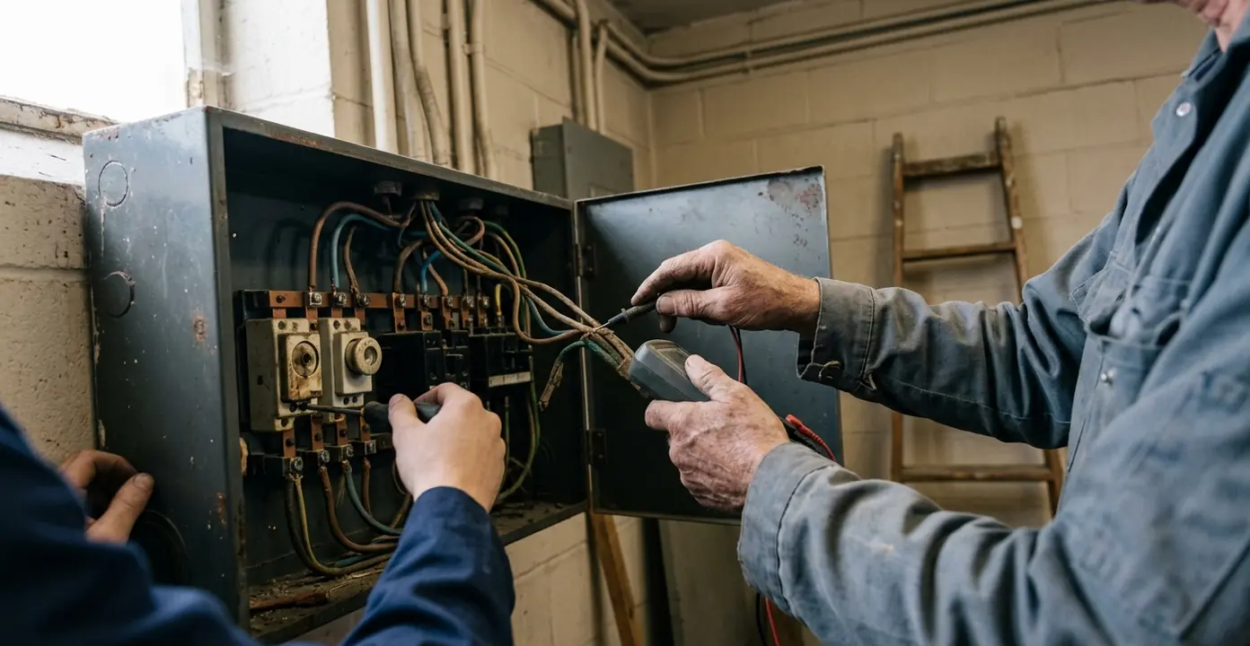
The Silent Threat in the Switch Room
At 09:15, during the morning peak, a facility manager stands in the basement switch room of a 1980s office block. The lighting is poor, the distribution equipment hums, and an obsolete breaker has tripped. Staff upstairs are waiting for circuits to be restored while the peak-load window continues towards 11:40.
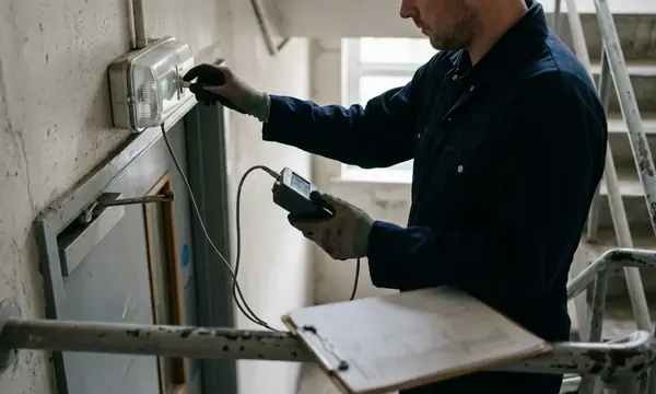
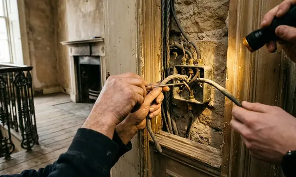
The enclosure is warm to the touch. A faint ozone odour hangs near the outgoing ways, where brittle thermoset plastic surrounds show their age. None of these signs confirms the cause in isolation, but together they justify controlled isolation, inspection and testing before anyone attempts a reset.
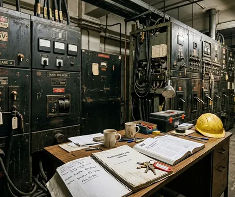
Ageing distribution boards often remain in service because they continue to supply power. That apparent continuity can hide loose connections, deteriorating insulation and persistent heat loss. By the time a board causes a complete outage, the underlying degradation may have been developing through years of ordinary commercial loading.
Ozone Means Stop
An ozone smell, unusual enclosure heat or visibly damaged insulation requires investigation under a safe isolation procedure. Repeatedly resetting a protective device can energise the same unresolved fault conditions.
Understanding the Anatomy of Electrical Degradation
Distribution-board deterioration follows a physical sequence. Commercial loads rise and fall throughout the working day, heating conductors, terminals and protective devices while current demand is high. Those components contract as the load subsides and temperatures fall.
How Thermal Cycling Develops
- Electrical load generates heat. Conductors, busbars and contacts warm during normal operation.
- Materials expand at different rates. Copper, steel, insulation and terminal assemblies respond differently to the same temperature change.
- Cooling reverses the movement. Daily load variation repeats the expansion and contraction cycle.
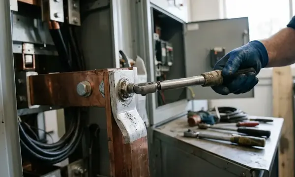
- Terminal pressure can reduce. Across continuous service spans of 18–30 years, repeated cycling can loosen connections from their intended terminal torque.
- Resistance and heat reinforce each other. A deteriorating contact creates more resistance, which produces further localised heating under load.
Insulation changes at the same time. Older materials harden, lose flexibility and may crack around stressed terminations or breaker housings. Dirt and moisture can then create less reliable surface conditions around already weakened components.
High-humidity basement switch rooms accelerate contact oxidation and insulation surface tracking far faster than dry, ventilated riser cupboards. Location therefore belongs in the condition assessment alongside board age, loading history and visible construction.
Inspection Errors to Avoid
- Judging condition from the enclosure door while leaving internal termination areas unexamined.
- Treating a satisfactory visual appearance as evidence that terminal resistance is acceptable.
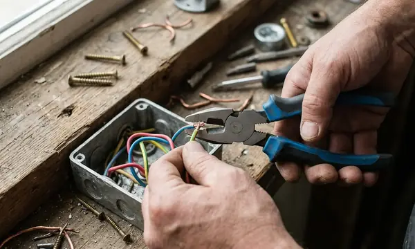
- Retightening connections without following the equipment requirements and an appropriate isolation process.
- Recording the board model but failing to establish whether compatible protective devices and spares remain obtainable.
When unexplained heat persists, the investigation should move from observation to load-aware compliance and testing. The board must be assessed under representative operating conditions where this can be done safely, since a lightly loaded enclosure may conceal a defect that becomes evident during the working-day peak.
The Hidden Financial Drain of Energy Inefficiency
Every resistive connection turns part of the supplied electrical energy into heat. In an ageing board, elevated resistance can develop at busbar joints, breaker contacts and terminations. That energy remains inside the enclosure rather than serving the building load.
A single warm connection may appear financially minor. Across a multi-floor distribution network, persistent losses accumulate at every affected point and continue whenever current flows. The same heat also places further thermal stress on nearby insulation and switching components.
Metering Determines What Can Be Found
Older boards commonly provide no native smart metering or per-way current transducers. The facility team may receive a whole-building utility total while remaining unable to distinguish lifts, mechanical plant, tenant areas or other individual high-draw circuits.
That lack of granularity restricts practical energy management. A change in total consumption can be seen, yet its circuit-level source remains hidden. Temporary measurement may help with a defined investigation, though it does not provide the continuous visibility available from integrated metering points.

- Review whether the board records current by individual outgoing way.
- Compare load information with operating schedules for the connected areas.
- Investigate circuits showing unexpected demand or heat rather than assuming the building total explains the cause.
- Include enclosure heat loss and metering capability in replacement planning, not only the cost of the board itself.
Useful energy monitoring starts at a level where action can be assigned. Without that detail, power-hungry circuits and degrading connections can remain buried within a normal-looking utility account.
Safety Risks and the Reality of Component Failure
Loose connections and compromised insulation raise the potential for arc faults and electrical fire initiation during normal commercial switching. The danger may develop without dramatic warning: a connection can heat locally while the rest of the board continues to operate.
Routine commercial infrastructure assessments across the UK repeatedly encounter older boards whose final circuits lack modern RCD and AFDD protection. Board condition alone does not establish circuit-level compliance; the protective arrangement, circuit purpose and installation condition require assessment together. The UK Health and Safety Executive guidelines on electrical maintenance provide an official reference point for maintaining electrical systems safely.
Why a Small Fault Can Become a Long Outage
Obsolescence changes the recovery process. When a current production device fails, a compatible replacement may be available through an established supply route. An obsolete panel can require a search for scarce parts and verification that any proposed device is suitable for that exact assembly.
A single-device fault can consequently produce 2–5 working days of operational downtime while parts are located. During that interval, temporary arrangements may be limited by the affected circuits, board condition and safe working requirements.
Spare-Part Reality
Record the manufacturer, board designation, protective-device range and known spare availability before a failure occurs. A label saying only “main distribution board” gives the response team little useful information during an outage.
Substitution also carries risk. Physical fit does not establish electrical compatibility, fault-rating suitability or approval for use within the original assembly. Planned replacement gives the design team time to resolve these questions before operational pressure encourages a hurried decision.
Insurance Implications and Compliance Standards
Commercial insurers increasingly request evidence of distribution-board age and condition during policy renewal. Useful evidence includes inspection records, identified defects, maintenance actions and a clear plan for equipment that has reached an advanced stage of degradation.
Where an electrical incident is traced to neglected equipment, an outdated board can contribute to premium loading or a coverage dispute. The policy wording and disclosed condition of the installation matter, so landlords should retain dated records rather than rely on informal assurances that the power has remained on.
How BS 7671 Fits the Decision
An installation that predates current BS 7671 protective-device expectations is not automatically unlawful solely because of its age. Its continued condition and suitability still need to meet the safety thresholds expected in current commercial occupation and lease arrangements.
A practical compliance review should establish:
- which protective measures are present on the relevant final circuits;
- whether identified defects require immediate action or planned improvement;
- whether alterations have introduced loads the original distribution arrangement was never designed to support;
- whether inspection and maintenance records can be produced for an insurer, landlord or incoming tenant; and
- whether obsolete equipment can be maintained safely for the intended occupation period.
Clear records support a more defensible decision. They show the board’s actual condition, the actions taken and the basis for any replacement programme.
Calculating the ROI of Proactive Replacement
The replacement case should combine operational exposure with direct cost. Facility teams first compare continued reactive repair against full board replacement. The reactive path becomes difficult to support once repeated call-outs, ongoing heat losses and the consequences of an unplanned outage are placed in the same model.
Build the Payback Window Step by Step
- Define the remaining occupation horizon. A typical evaluation examines 7–12 years of expected building use. Short-hold or demolition-scheduled assets rarely provide enough time for energy and downtime savings to accrue.
- Record reactive maintenance demand. Include emergency attendance and repeat work associated with obsolete devices or deteriorating terminations.
- Estimate avoidable heat loss. Use measured electrical and thermal findings where available rather than assigning a generic efficiency gain.
- Price operational interruption. Consider the effect of 2–5 working days without affected services if an obsolete component cannot be sourced promptly.
- Review insurance terms. Establish whether documented replacement would change policy conditions, premiums or renewal discussions. Any benefit should come from the insurer’s response, not an assumed discount.
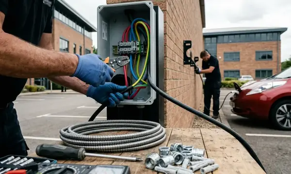
- Include future connection work. Modern boards can provide the headroom and metering points required for later EV charging systems and on-site generation connections.
Future capacity deserves particular attention in commercial infrastructure planning. EV charger integration can introduce sustained loads and a need for better circuit-level monitoring. On-site generation may require suitable connection points, protection and power-flow visibility. A modern board designed with these requirements in mind can avoid a secondary switchgear rebuild when those projects proceed.
Check the Installation Route Early
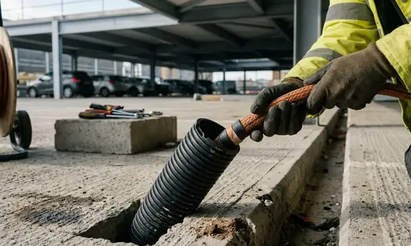
Replacement programmes often stall because the existing cable entries or floor voids cannot accommodate the depth of a modern board without structural alteration. A site survey should confirm access, cable reach, containment, isolation boundaries and working space before the financial case is approved.
The strongest ROI model uses a defined scope and evidence from the installation. It separates confirmed savings from possible benefits and sets the payback against the period in which the landlord expects the property to remain commercially occupied.
A Modern Infrastructure in Practice
After commissioning, a commercial landlord pauses in a bright plant area with a tablet in hand. Live per-way load and temperature values flow from the new distribution board’s integrated metering, allowing an unusual circuit reading to be located without opening the enclosure.
The board runs without audible contactor chatter or excess enclosure heat. Upstairs, the building continues through its working day while the landlord watches the dashboard settle into a clear, steady pattern and closes the switch-room door with the condition of the electrical infrastructure visible at last.