
What Periodic RCD Testing Checks on Commercial Boards
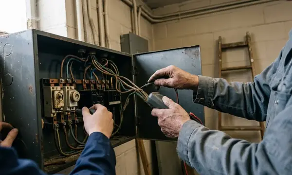
Periodic residual current device (RCD) testing combines instrumented verification of the trip mechanism and disconnection time under simulated earth-fault current with operation of the integral test button. On commercial distribution boards, the task starts with identifying what each protective device disconnects.
A mixed board containing residual current circuit-breakers with overcurrent protection (RCBOs) and split-load residual current circuit-breakers (RCCBs) presents different outage boundaries. An RCBO disconnects its associated circuit; an RCCB can disconnect several outgoing circuits together. Servers, EPOS terminals and HVAC controls therefore need an agreed shutdown sequence before injection begins.
Keep Button Checks and Timed Tests Separate
The quarterly user check associated with the installation notice operates the integral T button. It exercises the device through its internal test circuit. It neither measures disconnection time nor compares operation on the two test half-cycles.
Instrument testing belongs within the Electrical Installation Condition Report (EICR) or planned maintenance regime under BS 7671 and IET Guidance Note 3 (GN3). The button check cannot supply the disconnection-time entry on the Schedule of Test Results. For commercial infrastructure, the maintenance plan should identify both activities and allocate responsibility for each.
Select the Tester Range from the RCD Markings
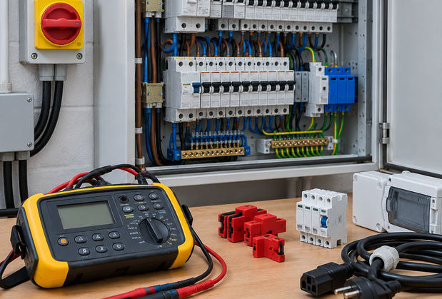
Read the device face before configuring the multifunction tester (MFT). The rated current, rated residual operating current, written as IΔn, waveform sensitivity and any time delay all affect the test selection.
- Type AC: responds to sinusoidal alternating residual current.
- Type A: also responds to pulsating DC residual current.
- Type F: adds sensitivity to composite frequencies associated with single-phase drives.
- Type B: adds smooth DC residual-current detection.
- Type S: identifies selective, time-delayed operation and requires the corresponding timing assessment.
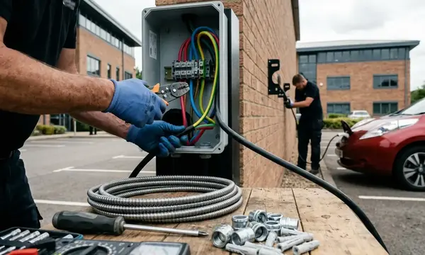
Variable-speed drives, switch-mode power supplies and EV charging systems make waveform selection important. Pulsating or smooth DC components can impair an unsuitable Type AC device. A successful AC-range test alone does not establish that the selected protection suits those loads.
Use an instrument conforming to BS EN 61557-6, with the waveform ranges needed for the installed device. Type B verification requires suitable smooth-DC test capability.
Clear the Load Before Measuring the Device
Disconnect or isolate downstream loads and surge protection devices (SPDs) from the test path before injection. Standing leakage and capacitance can distort the result; connected electronics can also be exposed to the test. Confirm the isolation arrangement rather than assuming that a local control switch disconnects the load.
This preparation gives the recorded trip time a clear meaning: it describes the RCD or RCBO under test, without the connected circuit contributing leakage current.
Plan the Shutdown Before Opening the Distribution Board
The facility manager and affected tenants should agree the outage against the circuit chart. Identify grouped RCCB circuits, refrigeration supplies and equipment requiring an orderly shutdown. Resolve suspected borrowed neutrals before testing: an unmarked shared neutral can operate an adjacent RCD or produce a misleading failure.
Write the permit-to-work around access, shutdown, testing and restoration. A regional projects programme should retain this board-level detail at each site; a common maintenance date does not establish which tenant can tolerate an interruption.
Remove Covers Under Safe Isolation
- Identify and isolate every relevant supply, then apply lock-off and retain control of the isolation.
- Prove the voltage indicator, test all relevant conductors for dead, and prove the indicator again. On a TP&N board, include the phase and neutral combinations relevant to the work.
- Remove the front cover only after proving dead. Complete any conductor disconnection and test-access preparation while isolated.
- Establish barriers and controlled access before re-energising for instrument injection. Restore covers or suitable guarding wherever practicable.
Competent personnel should carry out the work using PPE selected through the electrical risk assessment. Barriers must keep other plant-room users outside the test area. PPE supports those controls; it does not make exposed live work routine.
Inspect leads, insulation, finger barriers and probe tips before use. GS38 guidance specifies exposed conductive tips not exceeding 4 mm. Refer to HSE guidance on electrical test equipment (GS38) when selecting and checking the test equipment.
Run and Record the Device-Level Trip Tests
Apply the test connections at the load-side terminals of the RCD or RCBO using the instrument manufacturer's arrangement. Prepare connections under isolation. Disconnect the outgoing conductor or open suitable downstream isolators so that loads and SPDs remain clear of the injection path.
Use Ramp Testing to Investigate Operation
A ramp test helps investigate the operating threshold before timed testing. For a 30 mA device, the diagnostic band lies between 15 mA and 30 mA: the device should not operate below 0.5 × IΔn and must operate at IΔn. Establish the device response with the loads isolated before investigating connected-circuit leakage separately.
Record a ramp result as diagnostic information, keeping it separate from the required timed result.
Compare Both Injection Half-Cycles
- Confirm the device type, IΔn and tester waveform setting.
- Inject at 1 × IΔn, 0 degrees, and record the disconnection time.
- Reset the device, inject at 1 × IΔn, 180 degrees, and record that time.
- Enter the slower of the two times in the disconnection-time column. Record a non-trip explicitly as a failure.
General non-delayed devices have a 300 ms maximum at 1 × IΔn. Where the additional-protection verification requires a 5 × IΔn test, a 30 mA device receives 150 mA, with a 40 ms maximum.
Apply the correct timing category. A non-delayed 100 mA or 300 mA fire-protection device is assessed at 1 × IΔn against 300 ms. A Type S device uses its delayed operating band of 130 ms to 500 ms at 1 × IΔn. Applying the 40 ms additional-protection threshold to these devices would produce the wrong assessment.
Resolve a Refrigeration RCBO Failure Before Retail Opening
You have access at 06:30 to a 24-way TP&N distribution board; the retail tenant opens at 08:00. During the agreed 90-minute window, the 32 A Type A RCBO feeding back-of-house refrigeration trips on the 0-degree injection but fails on the 180-degree injection.
- Check the setup. Recheck lead connections and the MFT's lead-zero setting. Confirm that the compressor rotary isolators are open and the selected waveform matches the Type A device. Repeat the diagnostic ramp test.
- Check the mechanism. Operate the integral test button, reset the RCBO and repeat the failed timed injection. If it again fails to disconnect, condemn the device and immediately lock off the affected way before moving any outgoing conductor.
- Select the restoration route. Transfer to a spare way only where its RCBO matches the 32 A rating, Type A sensitivity, IΔn and phase, the neutral is dedicated, and the permit allows a second board isolation before opening.
- Make the transfer dead. Isolate and lock off the board again, prove dead, then transfer the line, dedicated neutral and CPC to the appropriate terminals for the spare way. Complete the necessary connection checks before re-energising.
- Verify and restore. Test the replacement arrangement, record both timed results and complete the affected circuit checks. Refit covers, restore refrigeration through its local isolators and confirm operation with the tenant. Enter the failed device and completed remedy in the maintenance record, leaving a documented, tested refrigeration supply ready for the 08:00 opening.