How Half-Hourly Metering Changed Commercial Reactive Power Correction
Reactive power correction developed around predictable industrial loads: bulk rotary condensers supported networks, while capacitor banks compensated induction motors. A fixed bank could follow a reasonably steady daytime requirement. Modern commercial infrastructure presents a different load profile, with variable-speed drives, LED drivers and EV charging systems changing demand throughout the operating day.
Half-hourly settlement made that timing financially visible. Smaller non-domestic maximum-demand supplies moved onto half-hourly settlement from 2017, with further commercial MPANs following through the early 2020s. Each day contains 48 settlement windows. A favourable monthly average can conceal individual windows with chargeable reactive import.
Where the applicable distribution tariff charges excess reactive energy, lagging demand can appear as a kVArh invoice line. The commissioning target commonly sits between 0.95 and 0.98 lagging, although the actual charging boundary must be checked against the supply arrangements. The Ofgem distribution connection and reactive power charging arrangements provide regulatory context; the site's tariff and invoice establish the charging test.
Why Fixed Banks Lose Their Fit
A bank sized around daytime motors can overcompensate an almost idle night shift. Conversely, changing charger and drive demand can leave individual windows undercorrected. Rectifier-based loads also introduce distortion that capacitors cannot simply cancel. Commissioning therefore needs separate checks for reactive demand, harmonic behaviour and stage control.
Turning Half-Hourly kVArh Records into Capacitor Stages
Begin with the supplier's half-hourly file, then compare it with measurements at the main LV incomer. The switchboard schedule identifies connected equipment; it cannot establish when that equipment actually demands correction.
- Collect aligned records. Log the incomer with a portable power quality analyser for 14 to 21 consecutive days, including a weekend and an overnight charging or late-shift period. Align timestamps with the supplier's settlement boundaries.
- Separate heavy and light windows. Identify recurring lagging demand, the lowest overnight load and changes associated with plant starts or fleet charging.
- Calculate the required correction. Use Qc = P × [tan(arccos PFexisting) − tan(arccos PFtarget)] for the displacement component that the bank can correct.
- Test the proposed stage sequence. Check that heavy windows reach the target band and that the smallest available step does not produce leading export during light-load operation.
As worked arithmetic, rather than a measured site result, 180 kW at 0.82 lagging represents about 126 kVAr. At 0.97 lagging, roughly 45 kVAr remains, giving a correction requirement of around 80 kVAr. Distortion needs separate assessment: applying the displacement calculation directly to a distortion-depressed total power factor can mis-size the bank.
Leave Room for Cooling and Fleet Demand
Modular stages, commonly 25 kVAr, allow later additions, but the smallest stage must suit the measured minimum demand. A mild fortnight with cooling plant stopped and the fleet idle will miss later reactive peaks. Allow controller capacity and physical provision for those additions across regional projects with seasonal operating patterns.
Night-Load Step Size
Choose the smallest step from the quietest credible operating window. A convenient catalogue increment can otherwise force leading operation overnight.
Using Harmonic Measurements to Select Detuned Reactors
Complete the harmonic survey before specifying or energising capacitive steps. Measure THD-V, THD-I and individual harmonic components at the main LV switchboard under peak and light load. Record several minutes of steady operation in each condition.
On a 50 Hz supply, examine the 5th at 250 Hz, the 7th at 350 Hz and the 11th at 550 Hz. Supply transformer inductance and an undetuned capacitor bank can form a parallel resonant circuit. If its resonant frequency approaches a significant harmonic, capacitor current and voltage distortion can increase, heating the bank.
Choose the Tuning from the Spectrum
- 7% reactors: tune the capacitor-reactor step to approximately 189 Hz, below the 5th harmonic.
- 14% reactors: tune to approximately 134 Hz and require consideration where a material 3rd harmonic is present.
- Thermal interlocks: prove each reactor winding thermal contact is closed when cold and connected into the stage contactor control circuit. Keep a stage disabled if its contact is already open.
These tuning choices require the measured spectrum and the equipment manufacturer's selection requirements. An idle-board snapshot cannot justify choosing between them.
Keep Untested Steps Open
On a drive-and-charger board, leave capacitive stages isolated until the survey establishes the reactor selection and the thermal protection circuit passes its checks.
Positioning CTs and Setting the Automatic PFC Relay
The controller must measure the combined effect of the site load and its own capacitor bank. Install split-core or solid-core CTs on the incoming conductors, downstream of the main incomer and upstream of the PFC feeder take-off. A CT fitted only around the PFC feeder measures capacitor current rather than the corrected site demand, encouraging hunting.
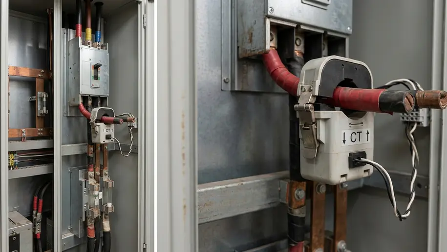
Use three-phase current measurement where EV chargers create phase imbalance. A single CT on L1 is suitable only where the logged operating cycle demonstrates adequate balance. Confirm the selected relay supports the intended measurement arrangement.
Prove Phase Association Before Automatic Switching
- Verify CT orientation and voltage sensing. Check primary direction, S1/S2 connections, phase rotation and the L1/L2/L3 sensing-fuse assignments against the relay wiring diagram.
- Set C/k sensitivity. A 25 kVAr step at 400 V draws close to 36 A. With a 600/5 CT, that corresponds to approximately 0.30 A secondary. Apply the controller's C/k convention, setting sensitivity just below a full step where its instructions require it.
- Enter the target and delays. Set the selected lagging cos φ target. Same-step reclose delays commonly fall between 60 and 180 seconds; use the capacitor manufacturer's discharge requirement to determine the setting.
- Configure protective lockouts. Enable the specified harmonic alarms and switching inhibits. Confirm that thermal trips prevent the affected stage from closing.
During a controlled manual test, closing one suitable step should reduce imported kVAr. An unexpected increase demands investigation of polarity and phase association before automatic operation. Isolate before changing wiring, and never open-circuit an energised CT secondary.
Verifying Stage Output and Proving the Billing Result
Test each contactor stage separately while sufficient lagging load is available. Measure L1, L2 and L3 with a true-RMS clamp meter and compare currents with the stage specification. Investigate unequal currents, contactor chatter or inconsistent switching; keep an unbalanced stage isolated while checking its capacitor, HRC fuses and connections.
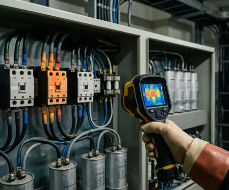
Establish thermal baselines after 45 to 90 minutes at full correction, once joints and windings have warmed. Record busbars, HRC fuse links and detuned reactor windings alongside load conditions. Compare equivalent phases and stages, and investigate localised heating before releasing the bank to unattended operation.
Keep the Evidence Open Through the Billing Cycle
Record stage currents, controller settings, CT details, harmonic measurements and thermal images in the commissioning pack. Then reconcile 30 days of post-commissioning half-hourly kVArh against the corresponding DNO reactive-charge invoice entries, including entries passed through by the supplier. Check overnight windows as carefully as daytime peaks, and investigate any remaining charge.
Keep final performance sign-off open until that 30-day reconciliation confirms the reactive charge line has cleared; an instantaneous power-factor reading is insufficient evidence.