The Regulatory Baseline for Commercial EV Infrastructure
BS 7671:2018+A2:2022 requires open-PEN detection or an equivalent protective measure for exterior EV charge points. Compliance leads should resolve that requirement before releasing the equipment schedule, particularly where a TN-C-S supply serves chargers positioned outdoors.
A broken neutral on a PME-fed charge point can raise the potential of exposed conductive parts and create a dangerous touch voltage. Omitting PEN-fault protection has contributed to touch-voltage incidents, so the protective method belongs in the initial design rather than a late variation.
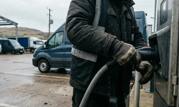
Workplace units commonly sustain loads from 7 kW to 22 kW across multi-hour shift patterns. Several vehicles may begin charging together when staff arrive, placing a sustained demand on distribution equipment that may already serve lighting, heating, machinery and office loads. This changes the commissioning brief from a basic final-circuit exercise to coordinated commercial infrastructure testing.
Set the Design Basis
- Confirm the supply type and proposed point of connection.
- Record whether PEN protection is integral to the EVSE or installed separately.
- Check the protective arrangement against the current requirements before procurement.
- Define how load management will respond to the site's available capacity.
The IET Code of Practice for Electric Vehicle Charging Equipment Installation provides useful technical context for translating the regulatory baseline into an installation method.
Site Surveying and Maximum Demand Analysis
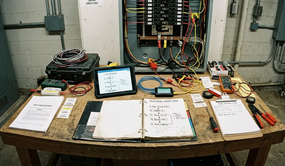
A useful survey starts at the incoming supply, not in the car park. Record the supply rating, distribution-board loading, protective-device details and the route to the proposed bays. Existing three-phase supplies on commercial sites frequently fall between 100 A and 400 A, yet the nameplate rating alone says little about usable headroom.
Survey teams commonly capture half-hourly maximum-demand readings over a continuous 10-to-14-day window. The selected period should include normal occupation, production and shift changes. These readings can then be compared with the proposed charger count and credible simultaneous demand.
Decide Where DLM Fits
- Establish the measured site maximum demand.
- Calculate residual capacity at the proposed connection point.
- Model simultaneous charging at the intended charger ratings.
- Specify dynamic load management where charging demand could exceed the available margin.
- Document the system's fallback behaviour if metering or communications fail.
Physical surveying needs equal attention. Drainage runs, expansion joints and fire-compartment walls can force containment diversions of 8 m to 25 m. Those diversions affect voltage drop, cable size, fire stopping and the final loop impedance.
Earthing Arrangements and Supply Types
TN-C-S supplies require particular care when charge points stand outside the equipotential zone of the main building. Remote bays, metal street furniture and wet ground increase the consequences of a PEN conductor fault.
Designers usually compare two routes: an open-PEN detection device that disconnects the EV supply under abnormal neutral-to-earth conditions, or a TT arrangement using a dedicated earth electrode. Open-PEN devices are required to disconnect when neutral-to-earth voltage exceeds 70 V for longer than a few seconds. Product instructions and the selected protective architecture determine the verification procedure.
Where TT Remains Practical
Exterior TT systems are commonly designed to achieve electrode resistance below 20 Ω. The measured value must still support the required disconnection performance and remain stable under the site's likely ground conditions.
TT conversion is practical only where soil resistivity and space within the site boundary permit electrode installation without crossing underground services or third-party land. This constraint can settle the decision before equipment cost enters the comparison.
Remote Bay Check: Do not assume that the building earth provides a suitable answer for a distant parking area. Confirm the conductor route, fault path and protective arrangement at the actual EVSE position.
Cabling, Containment, and Physical Mounting
Cable cross-section should follow a full-load voltage-drop calculation for the furthest bay. Long SWA routes across large car parks are especially sensitive to optimistic diversity assumptions. Where several 22 kW chargers can operate together, an understated design current can produce excessive voltage drop and a non-compliant loop impedance at the final unit.
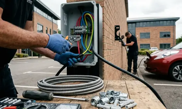
SWA suits many underground and exposed exterior routes. For a 32 A continuous load, the design should keep voltage drop below 5%, while also accounting for installation method, grouping, ambient conditions and protective-device coordination.
Fix the Route Before Civils Begin
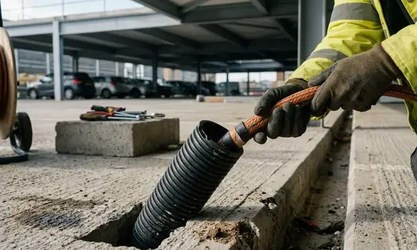
- Plot joints, bends, draw points and building penetrations on the coordinated route.
- Specify heavy-duty containment where delivery vehicles or maintenance equipment can reach it.
- Use impact-resistant bollards where chargers face vehicle movement; project specifications may require protection against contact from a 5-tonne vehicle at low approach speed.
- Run network data in separate-compartment trunking or maintain at least 300 mm separation from low-voltage power cabling.
- Keep charging leads clear of pedestrian routes and accessible paths.
Containment and mounting details should be agreed with the cable path. Moving a pedestal after cable sizing can add route length, alter bend requirements and invalidate the original voltage-drop calculation.
Electrical Testing and EVSE Verification
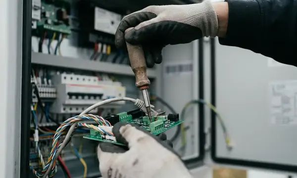
Dead testing comes first. Record protective-conductor continuity and insulation resistance before energisation. Insulation resistance is measured at 500 V DC, with 1 MΩ as the minimum acceptable value provided connected equipment has been isolated in accordance with the test method.
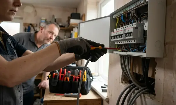
Live testing then confirms earth-fault loop impedance and prospective fault current at the charge-point terminals. Record loop impedance under no-load and simulated charging conditions. This exposes weaknesses that a measurement taken only at the upstream distribution board can miss.
Simulate the Vehicle States
A dedicated EVSE adaptor should simulate connection states A, B and C and provide controlled fault-test functions. Early reliance on a standard installation tester alone leaves the control-pilot sequence and EV-specific DC protection unchecked.
- Verify the disconnected state and absence of unintended output.
- Simulate vehicle detection and confirm the expected EVSE response.
- Simulate the charging-ready state and check contactor operation.
- Test RCD operation using the specified test sequence.
- Inject the required DC residual current to verify the RDC-DD response.
RDC-DD devices must detect 6 mA DC residual current and initiate disconnection within the times set by the manufacturer and BS EN 62955. Record the test condition, measured result and instrument used; a simple pass mark gives the next tester too little information.
Documentation, DNO Notification, and Handover
The Electrical Installation Certificate should include the complete schedule of results and every EVSE-specific verification. Charger identifiers must match the site layout, distribution-board schedule and commissioning record so that a future inspection can trace each result to one physical unit.
Assemble the Notification Pack
The handover file should contain the signed EIC, single-line diagram, schedule of test results, site layout, protective-device settings and load-management configuration. Include the EVSE test sheets and the final settings for open-PEN protection or the measured TT electrode result, as applicable.
Most UK DNOs require notification of new EV charge-point installations within 28 days of commissioning. The correct process depends on the local network operator and may use an ENA connection form aligned with G99 or an equivalent demand-connection procedure. Treat notification as a controlled project task with a named submission date and retained acknowledgement.
Handover Gate: Do not release the installation for routine workplace use until charger labels, certificates, test records and the site drawing agree.
Before starting the next project, identify the local DNO and download its specific ENA EV connection form into the project file.