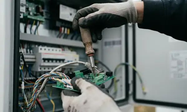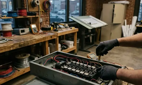
The High Cost of Switchgear Neglect
Switchgear maintenance often loses the budget argument because a healthy board appears to do nothing. It sits behind a locked door, carries load and attracts attention only when something trips. That apparent inactivity hides a concentrated operational risk.
Facility managers usually reach the same conclusion after comparing multi-year outage logs with the labour cost of a planned isolation. A controlled overnight shutdown has a defined scope. An unplanned failure can stop lifts, ventilation, production equipment, access controls and critical IT systems at once. If an arc-flash spreads through the assembly, adjacent panels within a radius hovering around 3 metres may be destroyed, turning a local defect into a complete suite replacement.
The replacement market makes that exposure harder to absorb. Custom medium-voltage switchgear assemblies currently carry procurement lead times trending toward 14 to 20 months. Temporary generation and revised distribution arrangements may keep part of a building running, but they introduce their own compliance & testing burden.
Budget The Isolation
Compare the cost of planned labour and lost operating hours with the full consequence of a switchboard outage. Include temporary power, tenant disruption, investigation, clean-up and the lead time for compatible replacement equipment.
Proactive maintenance changes the operating model. Known tasks enter the shutdown plan, defects receive priorities, and capital replacement decisions follow condition evidence rather than an emergency call.
Understanding Switchgear Degradation
Three processes dominate most maintenance findings: thermal movement, contamination and mechanical fatigue.
Daily load-driven temperature swings of 25 to 45 °C repeatedly expand and contract conductors, joints and supporting hardware. A bolted connection can look secure while its contact resistance slowly rises. Degradation tracking works best when bolted-joint resistance is logged at each annual outage and compared with load-cycle information from the building management system.
Moisture and airborne deposits attack from another direction. Urban industrial atmospheres can leave conductive films that measurably reduce creepage distance inside enclosures within 18 to 30 months if cleaning is neglected. Coastal western-Scotland sites need shorter cleaning intervals than inland offices because salt-laden air accelerates surface tracking on insulators.
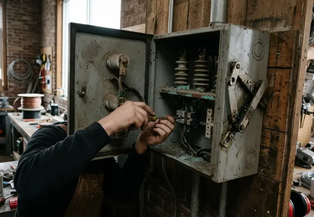
Moving components age even when they rarely operate. Springs relax, grease stiffens and linkages collect debris. Breakers left closed for years can seize when a genuine fault finally demands instantaneous opening.
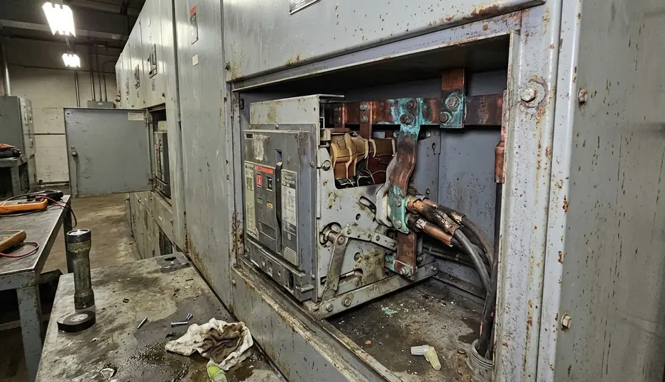
The useful maintenance question is therefore specific: which degradation mechanism can this task reveal or control? A visual round finds surface evidence. Thermography exposes heat under load. Insulation testing examines dielectric condition during an outage. Mechanical exercising confirms that a device can actually move.
Visual and Mechanical Inspections (Tasks 1 & 2)
Task 1: Inspect Visible Condition
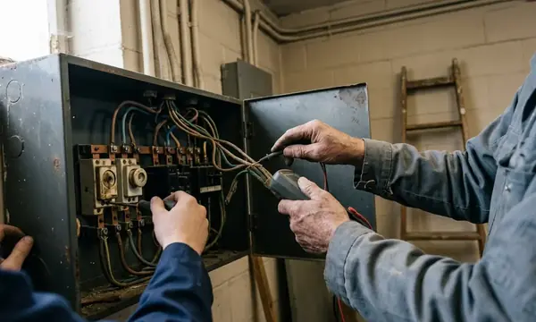
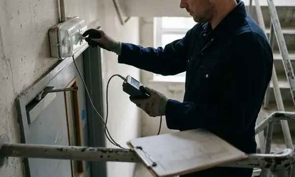
Start with a structured visual inspection of busbars, insulators, shutters, cable terminations, earthing conductors and enclosure joints. Record the location and extent of corrosion, cracking, dust deposits, loose components and signs of moisture. Photographs taken from the same position make gradual changes easier to judge at the next round.
Brown or blue temper colours at a busbar joint deserve immediate attention. These colours indicate prior temperatures above 150 °C, even if the joint feels cool during the inspection. Also look for melted labels, distorted insulation, tracking marks and soot around arc chutes.
Inspection cadence should reflect both manufacturer guidance and actual dust loading. Standard commercial premises commonly receive six-monthly visual rounds, while harsher environments move to quarterly checks. Those intervals are planning baselines; enclosure condition and operating duty should set the final schedule for each board.
Task 2: Exercise Breakers and Switches
Operate circuit breakers and disconnect switches through their permitted travel under the approved isolation procedure. Check that handles, charging mechanisms, shutters and interlocks move cleanly. Essential-circuit breakers receive a full manual open-close exercise every 90 days to keep mechanism grease mobile.
- Confirm the operating sequence and downstream impact.
- Isolate or transfer the affected load under the site switching procedure.
- Exercise the mechanism without forcing stiff components.
- Record abnormal noise, incomplete travel or delayed latching.
- Return the device to its documented service position and verify indications.
A clean-looking breaker can still have hardened lubricant inside its mechanism. Visual inspection establishes condition at the surface; exercising tests movement. Diagnostic work must follow where either task reveals heat damage, poor travel or deteriorated insulation.
Thermal Imaging and Insulation Testing (Tasks 3 & 4)
Task 3: Survey Under Representative Load
Infrared thermography is most useful when the switchboard has settled under a meaningful load. Schedule the route around building demand rather than technician convenience. Mid-morning peak periods often produce clearer signatures before afternoon demand falls.
Carry out the survey only after the board has carried at least one-third of nameplate load for a continuous 45-minute period. Compare equivalent phases and similar components, then record the actual load with each image. A warm joint becomes more significant when neighbouring phases under comparable current remain cool.
Load Before Lens
Thermal imaging works solely while equipment is energised and under normal load. An offline or lightly loaded backup board may contain a high-resistance connection that remains invisible to the camera.
Thermography also places personnel near energised commercial infrastructure. The survey method, access panels and safe working boundaries must follow the site electrical safety system and relevant HSE guidelines on electrical maintenance.
Task 4: Test Insulation Resistance
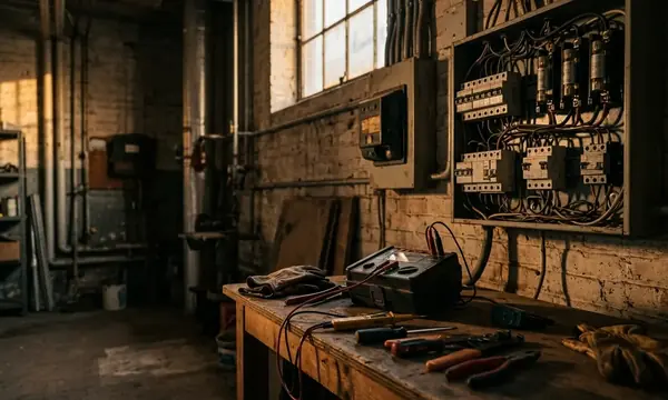
Insulation resistance testing requires a scheduled isolation, discharge and separation of equipment that could be damaged or distort the reading. For low-voltage testing, the stated method applies 500 V DC for a one-minute absorption interval. Where polarisation index is required, derive it from the 10-minute and 1-minute readings.
Trend readings against previous results taken under comparable conditions. Temperature, moisture, connected electronic devices and cable length can all affect interpretation. A single reading has less diagnostic value than a documented movement over successive outages.
Cleaning, Lubrication, and Torque Verification (Tasks 5 & 6)
Task 5: Remove Conductive Contamination
Cleaning controls the gradual formation of conductive paths across insulation. Dust, fibres, oil mist and salt deposits can hold moisture and encourage surface tracking. Work with the equipment isolated, proved dead and protected against re-energisation.
Use cleaning materials and methods accepted by the equipment manufacturer. Aggressive solvents can attack insulation, while compressed air can drive contamination deeper into mechanisms or spread it across adjacent compartments. Inspect vents, cable entries and damaged door seals before closing the board; otherwise the enclosure will quickly collect the same deposits again.
Cleaning and re-torquing outages are commonly confined to 3- to 5-hour overnight windows to avoid disrupting daytime commercial tenants. Good preparation matters. Stage approved consumables, drawings, torque values and access equipment before isolation begins.
Task 6: Verify Connection Torque
I favour the value marked on the manufacturer’s nameplate or current equipment documentation over a generic torque table. Different fasteners, plating systems, busbar arrangements and joint compounds change the required setting.
Use a torque wrench checked against a calibrated beam every 90 days, and verify it immediately after any drop onto a concrete floor. Mark completed joints in a controlled manner and record the applied value. Conductive lubricant belongs only where the manufacturer specifies it.
Torque Has Limits
Over-tightening can deform copper busbars, damage contact surfaces and strip threaded fasteners. Under-tightening raises contact resistance. The target value, tool condition and tightening sequence all matter.
If a connection repeatedly loses torque, investigate the joint rather than tightening it at every visit. Heat damage, incorrect hardware, poor alignment or loss of spring pressure may be driving the movement.
Protective Relay Testing and Environmental Control (Tasks 7 & 8)
Task 7: Prove Protection Performance
A relay indication proves that the device has power; it does not prove that the protection chain will trip at the intended threshold. Secondary injection tests the pick-up point and operating time by applying controlled current to the relay input.
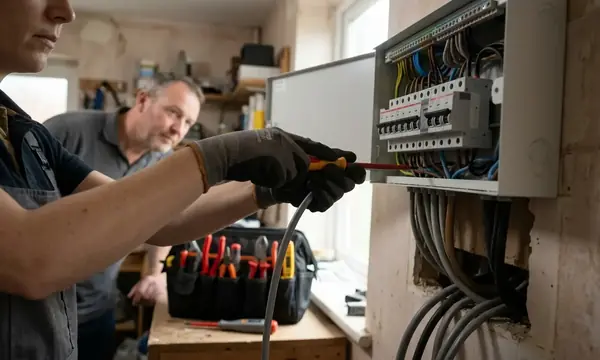
Test sets can drive currents from 0.1 A up to twenty times rated secondary to verify pick-up and timing curves. Confirm settings against the approved protection study before testing, then record both the injected value and measured operating time. Include the trip circuit where the planned test scope permits it.
Device technology determines the interval and method. Electromechanical units remain on a three-year secondary-injection cycle in the stated maintenance model. Stable microprocessor relays move to four- or five-year cycles. Solid-state equipment needs suitable diagnostic hardware and careful handling of stored settings, event records and communications.
- Check the relay model, firmware and active setting group.
- Verify current-transformer ratios and secondary wiring references.
- Test pick-up and timing against the approved curve.
- Confirm trip output, alarm indication and reset behaviour.
- Restore every temporary link and test switch before return to service.
Task 8: Control the Switchroom Environment
Ventilation, temperature and humidity belong in the maintenance programme because enclosure seals cannot compensate indefinitely for a poor room environment. Inspect for condensation marks, blocked vents, water entry, failed heaters and storage that restricts airflow.
For switchrooms operating at 5 to 15 °C ambient, continuous-duty wall-mounted dehumidifiers are used to hold relative humidity between 30% and 50% RH. Drain arrangements and humidity alarms need checks of their own. A dehumidifier that runs without removing water creates false confidence.
Regional projects should account for local exposure from the design stage. Salt-laden air, industrial dust and damp service spaces shorten the useful interval between inspections even when the installed switchgear is identical.
The Long-Term Value of Preventive Maintenance
The eight tasks work as a condition system. Visual inspection finds evidence, exercising proves movement, thermography identifies heat, insulation testing checks dielectric integrity, cleaning removes conductive deposits, torque verification controls joint pressure, relay testing confirms protection, and environmental control slows recurrence.
Documented maintenance histories can extend the practical service life of well-kept switchboards beyond their original 25-year design horizon. A cost model can compare three emergency call-outs with a decade of scheduled labour and materials.
The smallest defect provides the sharpest reason to act: a single loose joint dissipating in the ballpark of 8 to 12 W of continuous I²R heat can drive local copper beyond its annealing threshold within on the order of 14 to 22 months under typical commercial load profiles.