
Plant upgrades often begin with a tidy connected-load schedule and end at an awkward question: can the existing supply carry the equipment when the site is genuinely busy? For EV charging systems, heat pumps and heavy machinery, the answer comes from measured demand, operating constraints and the rating of the whole supply path.
The main switch, DNO fuse and incoming service set the boundary. A spare way in a distribution board does not establish spare electrical capacity.
How Commercial Power Demand Outgrew Legacy Boards
Light-industrial installations designed through the 1980s and 1990s had relatively predictable demand. Designers worked from lighting, basic HVAC and plant nameplates, then applied the accepted IEE diversity assumptions of the period. Once the main distribution board and incomer were selected, that design position tended to remain fixed.
Many 100 A three-phase incomers were left with only 10–20 A unused after the original plant was connected. LED retrofits later reduced lighting current, but the released capacity was rarely measured. It appeared as assumed headroom on drawings and in maintenance discussions.
Electrification Changed the Load Shape
The shift became pronounced in the early 2020s, when 40–60 kW commercial heat pumps and 22 kW AC chargers began appearing on those same supplies. These loads can coincide for long winter periods. The original lighting and intermittent-machinery diversity assumptions do not describe that operating pattern.
This matters because decarbonisation changes the baseline rather than simply adding another occasional circuit. A heat pump may be working hardest while vehicles remain connected for several hours. Legacy commercial infrastructure needs a fresh maximum-demand assessment before either load reaches procurement.
Connected Load and Maximum Demand Answer Different Questions
Connected load is the sum of equipment nameplate ratings. It belongs on drawings because it is auditable and useful for circuit schedules. Maximum demand is the highest demand the installation is expected to place on its supply during real operation.
Diversity can still be applied to genuinely intermittent lighting and machinery. Its use needs a defensible operating basis. A 22 kW three-phase AC charger draws 31.8 A per phase at 400 V, commonly treated as 32 A for the assessment, and can hold that current throughout a charging session.
Why Charger Current Stays in the Calculation
Charge windows of four to eight hours are treated as continuous duty. Standard diversity tables used for lighting and intermittent machinery are therefore not applied to the charger legs. Two 22 kW chargers contribute 32 A each on every phase unless an engineered control arrangement limits or sheds their load.
Charger Headroom
Do not infer capacity from unused breaker ways. Enter each uncontrolled charger at nameplate current, then compare the result with measured site demand and the ratings upstream.
Theoretical schedules also miss shift changes, simultaneous starts and seasonal HVAC operation. Before specifying breakers for substantial new plant, I treat the connected-load drawing as the audit trail and the logged maximum demand as the design input.
Running a Seven-Day Power Quality Survey
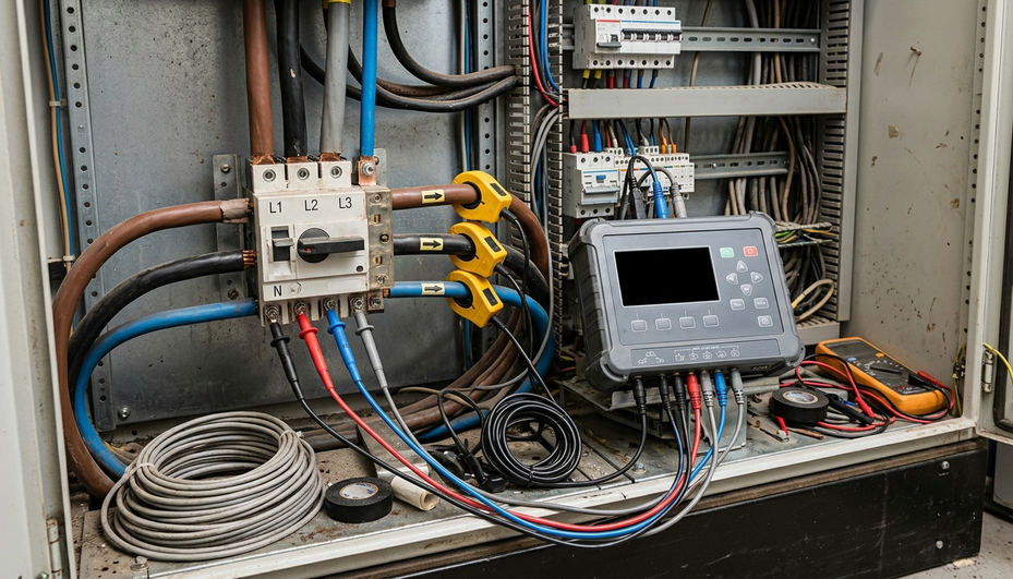
A useful survey covers one complete operating cycle. A single weekday trace can miss the weekend baseline and the Sunday-to-Monday plant restart, making it unsuitable as the maximum-demand figure for a Scottish DNO capacity application involving EV and heat-pump plant.
Logger Installation
- Confirm safe access, isolation requirements and the logger’s voltage category before opening the board.
- Fit clamp-on current transformers to the incoming tails or the load side of the main switch. Check orientation and assign the clamps correctly to L1, L2 and L3.
- Connect voltage leads to L1, L2, L3 and neutral so current, voltage, kW, kVA and power-quality readings share the correct phase reference.
- Install a second logger on the sub-board intended to supply the new plant where local loading could constrain the design.
- Record site events such as shutdowns, production changes and unusual plant operation alongside the trace.
Capture and Review
Run the logger for at least seven consecutive days, typically from Monday 00:00 through Sunday 23:59, using demand intervals between one and five minutes. Review the highest kW and kVA, the peak current on each phase, phase imbalance and voltage total harmonic distortion before selecting new protective devices.
Phase current deserves close attention. A seemingly acceptable three-phase average can conceal one heavily loaded phase. Harmonic readings may also point to loads that need investigation before further electronic equipment is added.
The trace describes the plant that operated during that week; equipment shut down for the whole survey remains outside the measurement. Check the operating diary before accepting the peak.
When Supply Capacity Requires a DNO Application
The decision point is direct: add the proposed plant current to the highest logged phase demand, then compare that result with both the DNO fuse and main-switch rating. Exceeding either rating stops the installation design at its present capacity.
Load shedding or time-of-use sequencing may recover headroom. These approaches work only where the operating rules are enforceable. If the heat pump and EV charging systems must run together during winter, an informal promise to stagger them offers no dependable protection.
Opening the Capacity-Increase Route
Submit a formal capacity-increase or new-connection application to the relevant Distribution Network Operator. The package should identify the existing supply, logged maximum demand, proposed equipment, phase arrangement, operating profile and any managed-load controls. The Energy Networks Association guidelines for new connections provide the wider connections route.
Programme risk can be substantial. A straightforward low-voltage capacity increase on an existing service can take several months from application to energisation. Where high-voltage feeder reinforcement is required, the period can extend beyond a year, with connection charges reaching five figures. Put that path ahead of charger or heat-pump delivery dates.
Worked Capacity Check for Two Chargers and a Heat Pump
Take a light-industrial unit with a 100 A three-phase supply. Seven-day logging records a highest phase current of 45 A. The proposed upgrade comprises two 22 kW chargers and a 50 kW heat pump with a 72 A running current at the design outdoor temperature.
Calculate the Coincident Current
- Start with the highest logged phase demand: 45 A.
- Add charger one at continuous-duty current: 32 A.
- Add charger two on the same basis: 32 A.
- Add the heat-pump running current: 72 A.
- Calculate the total: 45 A + 32 A + 32 A + 72 A = 181 A per phase.
- Compare 181 A with the existing 100 A DNO fuse and 100 A main switch. The proposed coincident load exceeds both ratings by 81 A.
The 181 A figure assumes both chargers and the heat pump run together on a 400 V TN-C-S three-phase service. A current-limited or interlocked charger pair would require a separate control-based calculation.
For this project, record 181 A as the uncontrolled design demand, halt breaker selection, test whether an interlocked charging scheme meets the operating brief, and open the DNO capacity application if simultaneous winter operation remains required. That sequence gives the facility manager a clear decision before orders are placed: retain the 100 A service only with verified load control, or obtain an upgraded supply for the full coincident load.