Why Can Lower-Wattage Upgrades Leave a Switchboard Hotter?
Why does replacing legacy inductive equipment with LED arrays and inverter-driven plant sometimes leave a commercial main switchboard running hotter than before? In the multi-storey office case examined here, the replacement programme reduced the scheduled kW load, yet the main neutral bar and transformer tank ran warmer during the first full occupied winter afterwards.
The LED and VSD replacements took place between April 2022 and August 2023. Before committing to larger switchgear, the investigation turned to the shape of the current waveform and its route through the building.
Lower kW Can Conceal Pulsed Current
LED drivers and rectifier-fed equipment draw non-linear current. Their input circuits can take short pulses around parts of the voltage waveform rather than drawing a smooth sinusoidal current. Those pulses introduce harmonic components: currents at multiples of the fundamental supply frequency.
On each office floor, dozens of single-phase drivers shared a lighting sub-main. Their individual ratings looked modest on the load schedule. At the shared riser and main board, their combined current waveform mattered considerably more.
Lower energy consumption and acceptable power quality require separate checks. Harmonic currents increase conductor heating and transformer losses, while the resulting voltage distortion depends on the impedance of the shared distribution network. A replacement schedule organised around watts alone misses that interaction.
For commercial infrastructure, the assessment also has two boundaries. Engineering Recommendation G5/5, issued by the Energy Networks Association in 2020, addresses harmonic assessment at the point of common coupling. The IET Wiring Regulations (BS 7671) govern the customer installation, including conductor selection and protective arrangements.
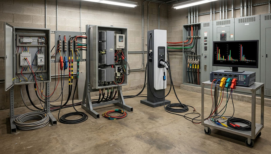
How LED Drivers, HVAC Drives and EV Charging Differ
The useful comparison starts with harmonic order, phase connection and operating time. Nameplate kW alone gives little indication of which conductor will carry the additional burden.
LED Drivers Load the Neutral
The office lighting sub-mains supplied single-phase drivers with prominent third- and ninth-order components. On the building’s supply, these corresponded to 150 Hz and 450 Hz. These triplen harmonics return in phase through the neutral of a three-phase star distribution system, so balancing the fundamental phase currents does not cancel them.
Lighting operated from about 07:30 to 19:00 on occupied weekdays. That long, repeatable period made the lighting riser a sustained neutral-loading concern rather than a brief starting event.
Six-Pulse VSDs Stress the Mechanical Supply
The HVAC drives used three-phase six-pulse diode rectifiers. Their characteristic fifth and seventh harmonics appeared at 250 Hz and 350 Hz. The fifth is negative-sequence, producing a counter-rotating magnetic field where that voltage component reaches rotating machinery; the seventh is positive-sequence. Both contribute to additional losses.
The operating schedule mattered here. Recovery from night setback brought mechanical plant demand up while lighting was already on and staff were arriving.
EV Charging Changes Through the Session
The dedicated workplace feeder served AC charging points in the 11 kW and 22 kW classes. The harmonic load seen by that feeder depended on the connected vehicles and their charging state. Bulk charging and the later taper produced different spectra, making a single charging-session measurement an incomplete basis for filter selection.
The critical overlap in this building ran from roughly 07:45 to 09:15: HVAC recovery, occupied-floor lighting and commuter charging shared the upstream board. That window gave the survey its operational focus.
What a Hot Neutral Reveals About Switchgear Stress
The most revealing observation came from the lighting riser. Its neutral bar was warmer than every phase bar, although the phase currents remained within around 5 A of one another at a riser load above 100 A.
That combination directed attention towards zero-sequence harmonic return. Third-, ninth- and fifteenth-order currents add in the neutral, allowing its true RMS current to exceed the current in any individual phase even when the fundamental load is balanced.
Inspect the Whole Neutral Path
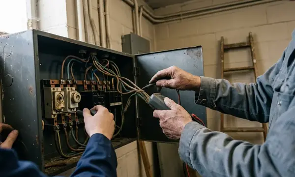
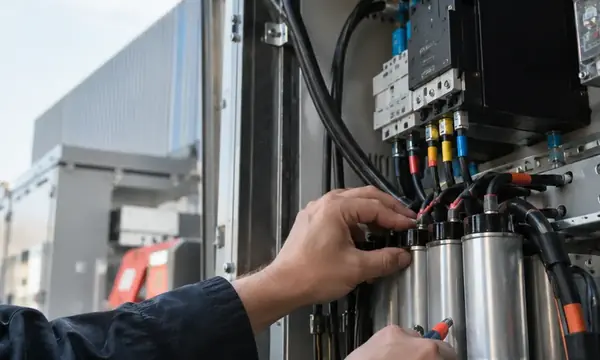
A thermal inspection should follow the return path through neutral links, busbars, cable terminations and four-pole devices. Reduced neutrals deserve particular attention, but a standard-sized neutral also needs checking against the measured harmonic load. Tightly packed risers increase the importance of the installation’s thermal conditions.
Localised heating still requires examination of the connection itself. A harmonic explanation should never displace checks on termination condition, conductor sizing and the distribution of heat along the assembly.
Separate Leakage Trips from Protection Selection
Drive and charger EMC filters can introduce high-frequency leakage currents. In the case building, nuisance tripping involved 30 mA devices, particularly Type AC units. Smooth DC residual current presents a separate concern because it can blind a Type AC device and impair its protective operation.
Replacing a tripping device with a less sensitive unit without checking the circuit’s protection requirements would miss the underlying issue. EV charging systems require the residual-current arrangement to be checked against BS 7671 Section 722, including Type B protection or Type A protection combined with 6 mA DC residual detection, as applicable to the equipment.
Reassess Transformer Heating
Transformer capacity also needs a harmonic-aware review. Eddy-current losses increase strongly with harmonic order, so a fundamental load below the original design value can coexist with elevated temperature. The appropriate loading assessment uses the measured spectrum and transformer characteristics rather than applying an arbitrary derating percentage.
Where to Log a Commercial Power Quality Survey
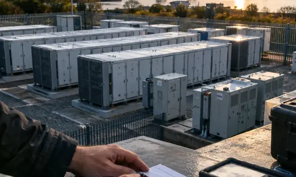
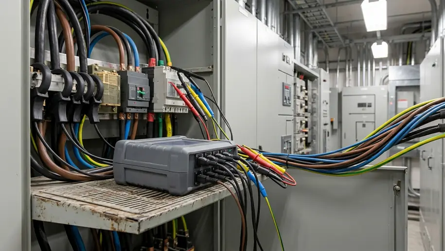
A single midweek clamp measurement at the main incomer initially produced a blended picture. It could not separate lighting triplens from the mechanical plant’s fifth and seventh harmonics or the changing EV load. The survey therefore moved to simultaneous logging at the main low-voltage board and the lighting, mechanical and EV sub-mains.
Capture the Building’s Operating Cycle
- Include occupied and base-load periods. The case survey ran from Friday through the following Thursday, capturing a weekend alongside the working week.
- Measure every return path. Rogowski coils recorded L1, L2, L3 and neutral simultaneously at the main board and each selected sub-main. Neutral current was measured directly.
- Keep current and voltage together. Record true RMS current, current harmonic distortion (THDi), voltage harmonic distortion (THDv) and the individual harmonic spectrum.
- Preserve the morning overlap. Higher-resolution records covered the period when lighting, HVAC recovery and arriving vehicles coincided.
Instrument installation belongs within a planned electrical safe-working procedure carried out by competent personnel. Sensor access, voltage connections and instrument ratings should be resolved before logging begins.
The case used 10-cycle measurement windows, equivalent to 200 ms at 50 Hz, stored as 10-minute aggregates. A separate 1-second record from close to 07:30 to 09:30 on two weekdays captured changes that longer averages could obscure. The retained spectrum extended through the twenty-fifth order, covering the principal components under investigation.
Read Percentages Against Actual Demand
High THDi on a lightly loaded feeder can attract disproportionate attention because its denominator, the fundamental current, is small. Review harmonic amperes alongside the percentage and compare the result with feeder loading.
Total Demand Distortion (TDD) uses demand current as its reference. It provides a different perspective when assessing distortion against building demand. Keep that reference consistent across comparisons, and examine THDv alongside current distortion to understand the effect on the supply waveform.
Thermography during the same morning window connected the electrical measurements with physical heating. Comparing neutral links and breaker terminations with phase-link temperatures made the findings actionable for compliance and testing.
Match Neutral Sizing and Filters to Each Feeder
The survey led to separate remedies for separate loads. This is a useful procurement discipline for regional projects: price the treatment against the measured conductor stress and harmonic spectrum, then verify the result under comparable operating conditions.
Larger Neutrals for Triplen-Loaded Lighting
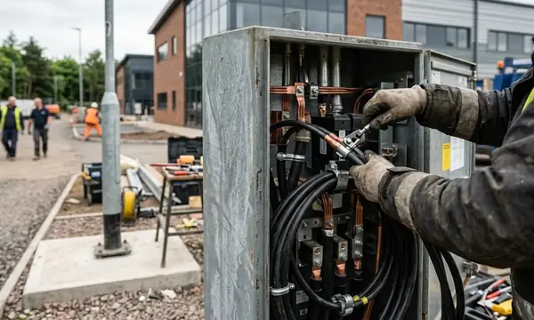
New lighting sub-mains in the case used a neutral cross-section twice that of the phase conductor. The design accommodated the measured triplen return current. It did not remove the harmonic current or correct voltage distortion.
That ratio was a project selection, not a universal BS 7671 prescription. Neutral sizing must follow the harmonic assessment, installation method, grouping and thermal conditions. Separate neutrals for individual single-phase circuits can also form part of a redesigned distribution arrangement, with each neutral sized for its actual duty.
Reactors and Passive Filters for Predictable Drives
The mechanical feeder suited treatment close to its six-pulse drives. Catalogue line-reactor options included 3% and 5% impedance; selection required checking the drive’s supply requirements and the resulting voltage drop.
A tuned fifth-harmonic trap was considered where the occupied-day drive load stayed steady. Passive equipment can offer a relatively economical solution for predictable loads, provided the design checks system impedance and resonance. A fixed HVAC treatment leaves the lighting neutral and changing EV spectrum requiring their own assessment.
Active Filtering for the Changing EV Load
The EV feeder received a wall-mounted active harmonic filter. Its current rating followed measured harmonic amperes during bulk charging, rather than the combined charger nameplate kW. Active correction followed the changing load within the cycle, making it suitable for the transition between bulk charging and taper.
Acceptance checks compared harmonic amperes, neutral current, voltage distortion and thermal behaviour under corresponding load conditions. The G5/5 assessment remained a separate check at the point of common coupling.
At commissioning, the chargers reach full output. The engineer enables the filter and watches the neutral-current channel fall beside the phase readings. On the analyser, the jagged phase-current trace settles towards a sine wave while the occupied building continues its morning routine.